
|
Make Mold using Assembly in SolidWorks Tutorial
|
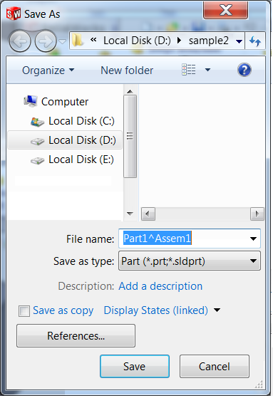
Make Mold using Assembly in SolidWorks TutorialStep 1 :Open Assembly part in SolidWorks.Go to File > New > assembly and click OK.  Step 2 :First of all, open the model that has to be create mold.Click the browser from the Feature-Manager tree and select the model name in the open dialog box and click ok.  Now make half mold on the left side.: Step 3 :Click the Inset Components > New Part from the Assembly toolbar in the Command-Manager toolbar.Click plus button of Part1 and select front plane. NOTE: Here I have a plane by the bottle model.  Step 4 :From the View toolbar above the Command-Manager, click the Top icon.From the Command-Manager toolbar, select the CenterLine command. Put a centerline in the middle of the model. From the Command-Manager toolbar, select the Center Rectangle command and draw a rectangle over the model. Close the sketch.  Step 5 :From the View toolbar above the Command-Manager, click the Trimetric icon.Click the Extrude Boss/Base command from the Features toolbar in the Command-Manager toolbar. Set the following: - Direction: Blind. - Depth: 70.00 mm. - Click OK .  Step 6 :Click Insert, Features, Cavity.Select the part which needs to be subtracted from the other part. Note: Select in the design tree not in the graphic area. Click OK. Close the part. 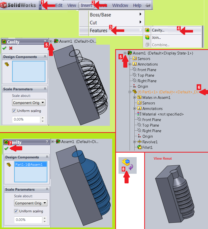 Now after that. Step 7 :Right-clicking on the original model part and select the hide component. Now make half the box on the right side.: Step 8 :Click the Inset Components > New Part from the Assembly toolbar in the Command-Manager toolbar.Click plus button of Part1 and select front plane.  Step 9 :From the View toolbar above the Command-Manager, click the Top icon.From the Command-Manager toolbar, select the Corner Rectangle command and draw a rectangle over the model. Close the sketch. Click the Extrude Boss/Base command from the Features toolbar in the Command-Manager toolbar. From the View toolbar above the Command-Manager, click the Trimetric icon. Set the following: - Reverse direction. - Direction: Blind. - Depth: 70.00 mm. - Click OK .  Step 10 :Click Insert, Features, Cavity.Select the part which needs to be subtracted from the other part. Note: Select in the design tree not in the graphic area. Click OK. Close the part.  Step 11 :Click the Exploded View from the Assembly toolbar in the Command-Manager toolbar.Click the part1.  Step 12 :Drag a manipulator handle.Similarly click the part2 and Drag a manipulator handle.  Step 13 :Right-clicking on the original model part and select the hide component. Save the every Parts : Step 14 :One by one Right-click on the parts of the finished assembly and click Open Part.When part open. Click Save icon and select Save as write the name and click Save. Parts Save. 
 Thanks. |
|
Share This:
|
Subscribe to:
Posts (Atom)
No comments:
Post a Comment